role of dielectric materials in flex circuit
In a flex circuit, the components and wires are mounted on a flexible substrate. Polyamide and polyester are the most commonly used materials for this purpose. In addition to establishing electrical connections, a flex circuit can also protect the sensitive electronics and components from mechanical stress or chemical reactions.
The circuit board’s dielectric material plays a critical role in this process. The dielectric material acts as a barrier between the copper conductors and the surrounding environment. Choosing the right dielectric material for an FPC requires consideration of the operating environment and the specific requirements of the product. For example, devices that are subject to high mechanical stress or chemically reactive environments might need a material like LCP or a polyimide/Teflon composite. Alternatively, consumer electronics that are less exposed to harsh conditions can use a polyester base dielectric.
A flex circuit can be single- or double-sided, and either way, the copper layers connect through metalized through-holes. These holes are then plated with copper to create a solid solder connection. Double-sided flex circuits are particularly useful because they reduce wiring errors and allow the component to be easily repositioned. In addition, they can be made more compact and lighter than traditional rigid PCBs.
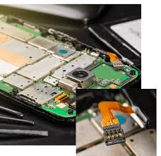
What is the role of dielectric materials in flex circuit?
As the number of connected devices increases, flex circuits have become increasingly important in the Internet of Things (IoT) ecosystem. These devices include wearables, medical implants, and other connected equipment. Because they are more versatile than rigid boards, flex circuits can be used to build a wide range of products.
Creating a flex circuit requires careful design and construction. The PCB must be able to support various types of stress without damaging the copper. This is why it’s important to consider the bend radius when designing a flex circuit. In order to ensure that the flex circuit will meet the desired specifications, it must be tested and evaluated before production begins.
The first step in creating a flex circuit is to design it using PCB design software. This will determine the expected mechanical and electrical requirements of the finished device, the placement of components, and the routing of traces. Once the design is complete, output files are generated and used to create the copper layers on the substrate. These layers are printed using a photochemical etching process.
After the copper layer is printed, a protective cover layer is placed on the flex circuit to protect it during manufacturing. A stiffener is added to help the flex circuit maintain its shape during bending, squeezing, and inserting. Finally, the flex circuit is plated with copper and the solder mask is applied.
Another important aspect of a flex circuit is the adhesive material that bonds the copper to the substrate. The adhesive is designed to withstand high temperatures, and different adhesives are used for different types of substrates. For example, a flex circuit made with a polyimide base will require an adhesive that is able to resist the decomposition temperature of the polyimide. Similarly, a copper-plated PCB will require an adhesive that can withstand the high temperatures used during soldering.